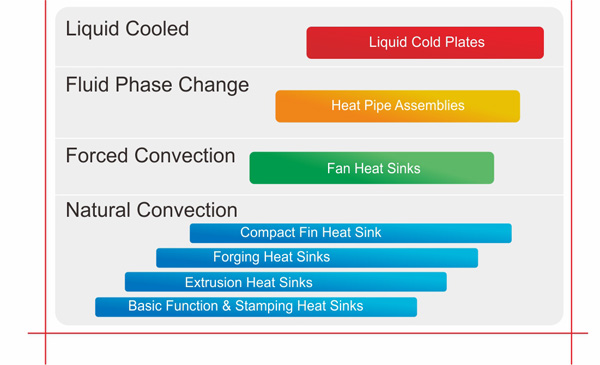
The graph above illustrates the relationship between the Power Dissipated in an application versus the Thermal Efficiency of a given solution. The X Axis indicates the total amount of power to be removed, while the Y Axis can be defined as the relationship of thermal resistance with respect to total power, unit volume, and heat flux density. This tool serves as the starting point for solving thermal problems by narrowing the field of available solutions.
Suitable technologies for an application can be identified by plotting the expected Power Dissipation on the X Axis and considering the entire range of intersecting along the Y Axis.
Dependent upon the power used and the dynamics of the system configuration, there may be more than one appropriate cooling mechanism to solve your thermal problem.
Four Primary Cooling Mechanisms
• Natural Convection applications do not rely on a specified local air velocity for heat dissipation. Typical natural convection heat sinks are passive in nature and manufactured from copper or aluminum sheet, extruded aluminum, machined or cast alloys, as well as fin assemblies.
• Forced Convection applications require forced air velocity generated through the incorporation of either a dedicated or system level fan(s) in order to increase thermal efficiency.
• Fluid Phase Change applications, also known as recirculating, typically employ closed loop heat pipes which allow the rapid exchange of heat transfer through evaporation and condensation.
• Liquid Cooling applications comprise channeled cold plates along with a heat exchanger and pump system in order to circulate fluids past a heat source. It is a physical loop.
 LED Light
 IT Server & Storage